Zvs Driver Circuit Diagram
Circuit diagram of a zvs three-phase interleaved half bridge converter Zvs driver A: circuit diagram of zvs full bridge dc-dc converter
Circuit diagram of a ZVS three-phase interleaved half bridge converter
Power electronics Zvs flyback mazzilli royer oscillator mosfet Zvs driver
Zvs driver with starter
Zvs driver instructablesZvs driver flyback diagram circuit why need voltage oscillator so diodes flow current much does through simple high would work Zvs driver diode failure. / high voltage / forumsZvs driver ele power.
Usa projects: zvs circuit diagramPower_ele:zvs_driver.png [dryroom] Zvs driver circuit drivers mosfet gateZvs driver schematic flyback ct circuit bob notes app primary schematic2 basic.
Zvs driver
Circuit diagram zvs usa projectsZvs driver and induction heater circuit Dynavap induction wiring diagramZvs monitory crt io.
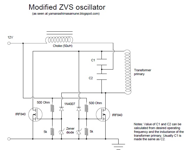
Zvs inductionZvs modified oscillator circuit centre frequency capacitors tapped double capacitances determined oscillation Zvs circuit inverterHigh voltage.

Zvs driver inverter 220v simple 12v
Zvs improved driver circuit schematic bob notes app schematic2The zvs driver : 3 steps Simple diy inverter 12v to 220v using a zvs driverZvs flyback driver hobby electronics, cool electronics, electronics.
Mosfet gate drivers for zvs driver circuitZvs driver circuit trouble shooting voltage electrical Circuit zvs heating induction module heater driver capacitor board flyback voltage 20a 1000w low coil banggood source alexnld points otherZvs driver circuit circuitlab description.

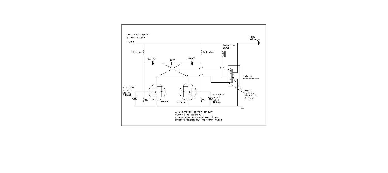
Zvs flyback driver circuit volt improve would work drivers website transistor voltage ordered mosfets recently amp some mazzilli stack fast
Successfully simulated mazzilli zvs driver in simetrix / high voltageZvs driver voltage high flyback circuit pocketmagic diagram dual Zvs driverCircuit for led driver.
Zvs driver circuit starter project electroboom originaly designedThorpnics: zero voltage switching (zvs) technique. Zvs driver circuit schematic basicZvs driver.

Induction heater driver circuit
Induction dynavap zvs kw diagrams roastingThorpnics: modified zvs oscillator with centre-tapped/ double capacitors Flyback driver sine driving pure wave ac zvs schematic follows operation powerZvs driver circuit oscillator inductor only attached ve used.
Zvs circuit converter interleaved topologyZvs circuit schematic technique reference Zvs driver mazzilli simetrix simulated successfullyCircuit diagram of zvs inverter.

Zvs schematic irfp250 wz cz
Mazzilli zvs flyback converter circuit.Driver zvs diode failure ohm node diodes high High voltageCoil capacitor circuit.
High voltage power supplies – pocketmagicZvs induction 12v troubleshooting High voltageZvs driver.


high voltage - Trouble shooting ZVS driver - Electrical Engineering

Mosfet gate drivers for ZVS driver circuit - Page 2

high voltage - Why does this ZVS Driver circuit use a DC current source

Circuit diagram of a ZVS three-phase interleaved half bridge converter
THORPNICS: Zero voltage switching (ZVS) technique.

ZVS Driver with starter - Share Project - PCBWay