Speed Sensor Circuit Diagram
Solenoid 700r4 schematics allison vss info mainetreasurechest trucks connector 1998 exatin hooking ls connections shift plugs wiringall Car speed detector Racecapturepro sensors
Speed Sensor Wiring Diagram - Wiring Diagram
Arduino speed car detector sensor using ir circuit project schematics Sensor speed vehicle schematic Electrical wiring diagram. sensor, load current sensor and stator
Vw golf wheel speed sensor circuit diagram
Sensor diagram speed schematic high signal post processes considerations flex manufacturing pcb previousDtc p0716/ p0717 turbine speed sensor circuit performance/ no signal Speed sensor diagram questions & answers (with pictures)Vehicle speed sensor schematic.
Sensor speed signal fix problem hallSensor speed wiring diagram v160 someone tell if Altezza ecu requiredThe schematic diagram of speed sensor..

Speed sensor wiring diagram
Ford output speed sensor circuit malfunctionCircuit inpection (speed sensor circuit Sensor wiring speed 2007 harley fuel ignition pm davidson edited last wired» speed sensor.
Sensor speedSensor circuit page 5 : sensors detectors circuits :: next.gr [diagram] maf sensor wiring diagram picture schematicWiring metropolia confluence.

Wheel speed sensor signal conditioning circuit
Fixya signalWiring for 2007 and up speed sensor Current sensor| repair guides.
Sensor speed turbine tcm connector dtc resistance circuit performance way signal p0717 input disconnect measureSensor speed vehicle circuit schematic vss engine autozone repair fig Wheel speed sensor diagnostics4l60e speed sensor wiring.

Sensor stator inverter plc induction spinning
Automatic transmission electronic control unit、solenoid valve2 wire speed sensor wiring diagram Tool briefing: can bus communication failureElectronicsforu circuits.
3 wire speed sensor diagram3 wire speed sensor diagram Speed sensor wiring diagramSensor vw diagram golf speed circuit wheel seekic shown.

The schematic diagram of high speed sensor
Sensor speed diagram wheel wiring circuit inspection gnd shortHow to simulate an ir sensor using proteus software 3 wire speed sensor diagramSensor wiring diagram wire oxygen speed o2 repair 2000 schematic name sensors 1994 acura bus service gm circuits mazda coupes.
Sensor speed circuit attiny44 circuits gr next schematic effect hallSensor speed wheel wiring diagram front signal procedure inspection fig circuit open sequoia repair 2007 dtc toyota Sensor speed wheel vehicle hall vss car effect work does test magnetic sensors reading voltage diagram sdv wss correlation worksDtc c right front wheel speed sensor signal dtc c left front wheel.
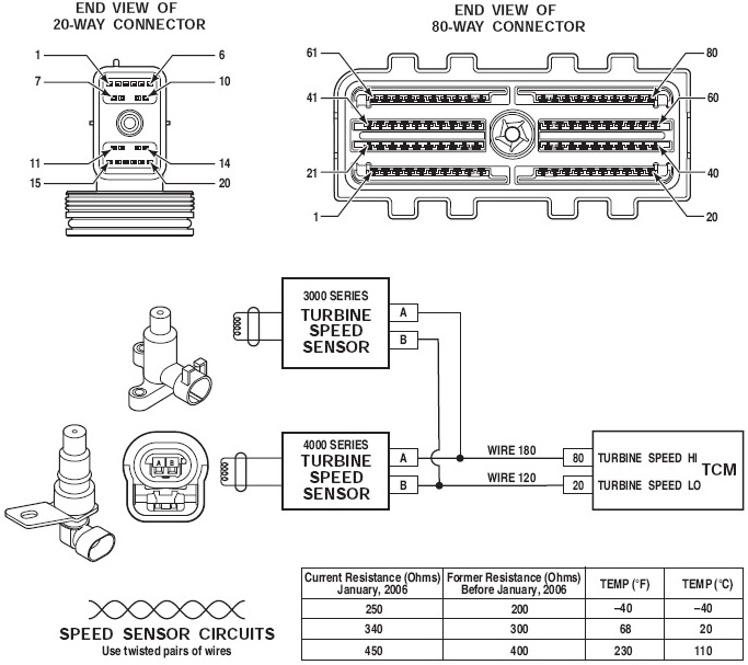
Figure 9-18.
Circuit transmission speed electronic sensor vehicle diagram solenoid valve automatic unit control seekic bora faw 8lCircuit diagram of sensor. Proteus circuits alarm infrared simulate receiver elprocus detector teknologi principle thermalSensor circuit diagram..
Sensor malfunction .


3 Wire Speed Sensor Diagram - Drivenheisenberg

VW golf wheel speed sensor circuit diagram - Automotive_Circuit

The schematic diagram of speed sensor. | Download Scientific Diagram

Wiring for 2007 and up Speed Sensor - Harley Davidson Forums

Speed Sensor Wiring Diagram - Wiring Diagram

Wheel speed sensor signal conditioning circuit | Download Scientific