Pwm Power Supply Circuit Diagram
555 pwm circuits generate generating explored simplest below Motor circuit pwm dc controller speed control circuits simple 24vdc diagram make based ic schematic mosfet 555 potentiometer current homemade Regulated circuit triac
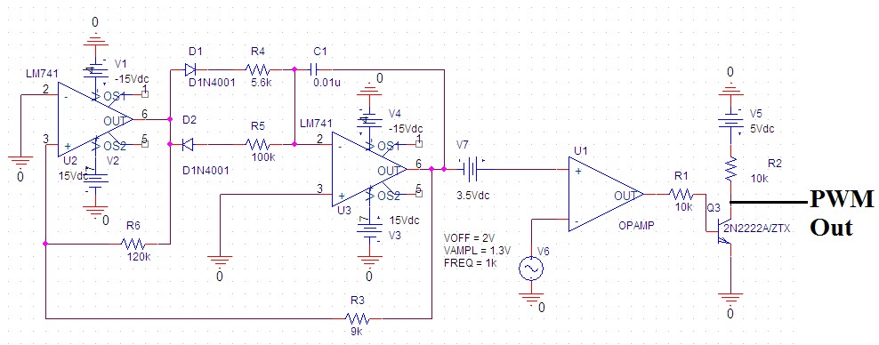
Electronic – Voltage to PWM Circuit, need to understand frequency
Circuit pwm schematic signal 5v 12v current schematics microcontroller result diagrams amplification convert mosfets controlling higher fertilizer duty drop heavy Pwm circuit dc volts diagram schematic help Pwm motor dc controller circuit ne555 diagram transistors darlington 555 dimmer led power using transistor voltage generator switch eleccircuit output
Help for pwm circuit for 12 volts dc up to 1.3 a
Motor controller speed 12v 4011 dc circuit simple ic pwm control using eleccircuit 24v current high volt cd4011 power 90vPower supply circuit diagrams Pwm circuit schematic pulse modulation width figureSaros electronics: october 2011.
Motor circuit dc pwm control 90v building schematic speed electrical 20amps work will resistors ballast electronics stack0-30v variable power supply circuit diagram at 3a Only wiring and diagram: december 20136amp_reg_pwrspl.

Pwm power supply circuit diagram
Pwm voltage circuitlabPower supply schematic diagram Pwm wiring diagram hydrogen current circuit limited detailed boardSupply power 30v dc adjustable circuit 3a diagram variable laboratory 2a current voltage 12v eleccircuit pcb transformer lm317 transistor constant.
How to make variable power supply circuit with digital control555 pwm dc motor controller circuit To the rails: april 2011Power supply circuit diagram schematic audio guitar amp diagrams control afiata amplifier schematics figure 100w.

555 pwm circuit ic simple using diagram use generating generate mode circuits monostable homemade configuration following learn let pinout easy
Electronic – voltage to pwm circuit, need to understand frequencyPwm motor control circuit – electronic circuit diagram Circuit diagram of pwm using 555Pwm circuit dc power electric layout motors drivers some application note.
Pwm circuit schematic using generating circuitlab createdHow to generate pwm using ic 555 (2 methods explored) Pre-regulated high voltage power supply circuit diagramMake this pwm based dc motor speed controller circuit.

Transformerless rangkaian volt trafo 120vac 5vdc dasar 1a sekema skema suply membuat relej vremenski fonte 230vac transformador rangkain transformer berhubungan
Power supply circuit audio control schematic diagram amp 2way diagramsCircuit pwm mosfet schematic channel motor protect driving when using dc result test automotive pump electrical electronics Schematic circuitlab circuitCircuit schematics.
Simple pwm motor control circuit using ic 4011Lm317 28v 20a variable ampere konstrukcja regulowany skuteczna zasilacz schematics powersupply regulator nte regulated 6amp Supply power 20a circuit 8v linear schematic diagram explanationSome power pwm drivers for electric dc motors.

Lm317 circuit supply power mcu work microcontroller does circuits pwm controlled schematic dc psu ac control opamp microcontrollers
Building a pwm circuit to control a 90v dc motor at 20amps. will this work?Pwm circuit schematic Pwm october larger clickPwm circuit dc drivers power electric layout picotech motors some gif.
Supply power circuit variable control digital 24v make working transformer rectifier bridge13.8v 20a linear power supply circuit and explanation Some power pwm drivers for electric dc motorsOperational amplifier.

Pwm wiring diagram
Pwm voltage module circuit diagram v1 codreyPwm motor control circuit speed using circuits dc controller diagram power schematic 2009 simple electric loop february closed Adjustable power supply schematic diagramTransformerless power supply circuit.
Inverter pwm sg3525 theorycircuit transformer frequency mosfet modulator sg3524How to generate pwm using ic 555 Pwm to voltage module (v1)Current limited pwm.

Power supply circuit diagrams | Schematic Power Amplifier and Layout

PWM to Voltage Module (v1) - Codrey Electronics
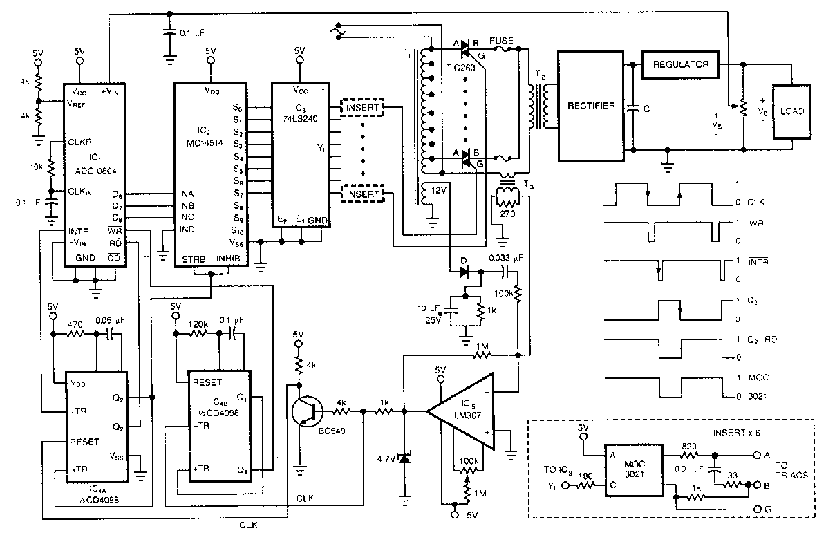
Pre-regulated High Voltage Power Supply Circuit Diagram

Building a PWM circuit to control a 90v DC motor at 20amps. Will this work? - Electrical

555 PWM DC motor controller circuit - ElecCircuit.com
To the Rails: April 2011