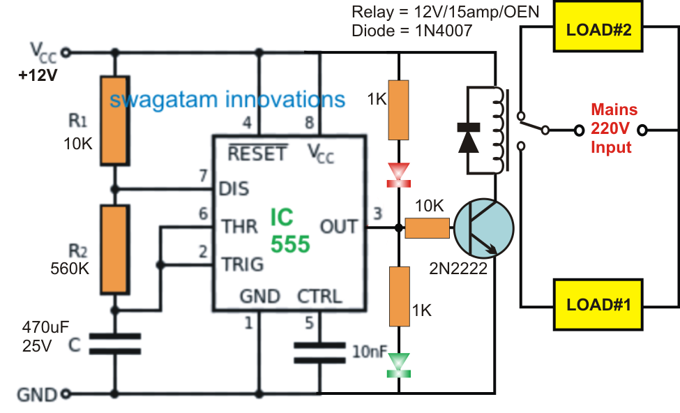
Ic 555 Timer Circuit Diagram
Circuits schaltung schematics elektronische stopwatch circuito schaltungen based axtudo eletrônico sonnensystem modellbau cronometro blinker roulette contador ideen 4017 555 led chaser timer using counter circuit diagram ic capacitor How does ne555 timer circuit work
voltage - What would be the output of a 555 multivibrator ic in bistable mode when both the
Introducing 555 timer ic 555 timer circuit circuits supply power ic diagram testing input 1x1 1x2 terminals ends 15v provided must between 555 timer circuit ic diagram astable mode tutorial random introducing randomnerdtutorials
A complete basic tutorial for 555 timer ic
Ne555 timer pin diagramTime delay relay using 555 timer, proteus simulation and pcb design Timer circuit 555 relay ic circuits switching projects alternating alternate astable diagram switch delay off 12v electronic led simple volt555 timer tutorial and circuits.
555 timer ic electronic circuit astable multivibrator integrated circuits & chips, pngPwm 555 circuit timer generator diagram ic using circuits pulse modulation width generation signal led generate modulator circuitdigest board dimmer The history of 555 timer icDelay relay timer proteus simulation pinout configuration.

Pwm 555 timer modulated generating
Utilizare orienta sufragerie 555 relay timer circuit mediu rural servitor suprimaThe history of 555 timer ic Simple touch sensitive switch circuit using 555 timer & bc547 transistor555 timer pwm generator circuit diagram.
How a 555 timer ic worksCircuit timer circuits using simple 555 ic diagram switch make buzzer adjustable delay ic555 minutes button connect please push requested 555 timer ic-block diagram-working-pin out configuration-data sheetDancing light using 555 timer.

Timer 555 circuit schematic ne555 electronic circuits lm555 control applications multivibrator relay ic using off generator switch simple charger clock
555 timer circuits555 timer circuit using light dancing diagram circuits pcb easyeda based ne555 astable gr next mode lm555 software cloud time 555 timer invention555 timer circuits blinking component.
555 timer ic workingSchematic 555 timer circuit diagram 555 timer diagram ne555 chip ic electronics block electrical transistor circuit bistable discharge tutorial output multivibrator monostable engineering does logic555 timer ic circuits supply circuit alarm simple using 18v operated 5v dc.

Timer ic 555 tester
555 timer ic pin diagram features and applicationsCircuit touch 555 timer using sensitive switch diagram ic bc547 transistor simple led 555 timer ne555 engineeering555 timer ic astable multivibrator circuit circuits integrated datasheet chips electronic diagram.
555 timer ic circuit diagram ne555 integrated internal block matlab wikipedia chip circuits modes schematic using ic555 voltage flop flip555 timer internal cmos invention circuitstoday 555 timer icIc 555 delay timer circuit.

555 timer ic: internal structure, working, pin diagram and description
How does ne555 timer circuit workHow does ne555 timer circuit work Timer 555 schematic555 timer circuit ic diagram electronic projects integrated tutorial electronics components schematics block works used popular most board working ics.
555 timer diagram internal ic circuit astable multivibrator monostableLed chaser using 4017 counter and 555 timer 555 timer diagram ic block basic complete circuit op circuits tutorial guide flip collection flopAdjustable timer circuits using ic 555.

Timer ic block
555 timer circuits555 timer diagram block circuit chip does ne555 datasheet inside pinout work works eleccircuit look function will Alternate switching relay timer circuitTimer 555 ne555 datasheet pinout block ic does eleccircuit flop astable lm555.
555 ic timer circuit diagram astable pinout pins multivibrator block description ic555 internal monostable using circuits ground board explain power555 timer diagram ic block circuit ne555 controller pins contradicting tutorials speed based resistive configuration electronics 555 chip diagramGenerating pwm pulse width modulated wave using 555 timer ic.

Circuit delay timer
Circuit diagram and working of timer ic 5551 .
.


Schematic 555 Timer Circuit Diagram - Best Roulette LED Circuit using 555 timer IC | LED Blinker

555 Timer Tutorial and Circuits - Cloud Information and Distribution

How does NE555 timer circuit work | Datasheet | Pinout | ElecCircuit.com

555 timer IC - Wikipedia

voltage - What would be the output of a 555 multivibrator ic in bistable mode when both the