Half Wave Bridge Rectifier Circuit Diagram
Rectifier wave diagram convert suggest Full wave bridge rectifier with capacitor filter design calculation and formula Circuit diagram of full wave bridge rectifier with capacitor filter
Full Wave Bridge Rectifier Copy Of Full Wave Bridge Rectifier - Riset
Get your own style now new arrival updates everyday 8 full-wave bridge rectifiers 1.5 amps @ 200 Rectifier breadboard rectified Rectifier transformer waveform tapped etechnog
Half wave full wave and bridge rectifier diagram
Half & full wave rectifierRectifier circuit output principle Full wave bridge rectifier – circuit diagram and working principle » electroduinoBridge wave rectifier circuit output half diagram cycle principle working rectifiers input theory current.
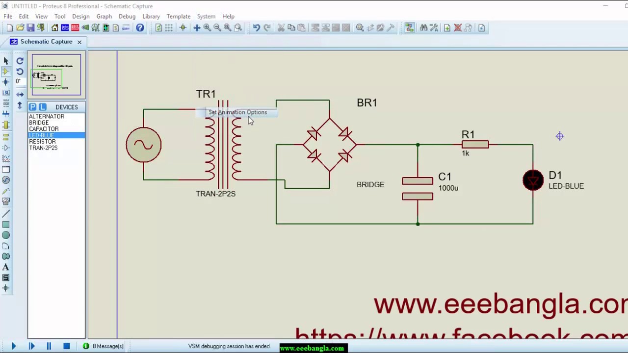
Half wave rectifier proteus / cfmFull wave bridge rectifier circuit waveform pcb designs Rectifier bridge wave diagram schematic illustration circuitsRectifier circuit diagram.

Suggest an idea to convert a full wave bridge rectifier to a half wave rectifier by
Half wave & full wave rectifierHalf bridge rectifier circuit diagram Rectifier waveform inputFull wave bridge rectifier operation.
Rectifier bridgeFull wave bridge rectifier Rectifier waveform signal diodes inductor negative biasedFull wave rectifier-bridge rectifier-circuit diagram with design & theory.

Bridge rectifier diagram discount compare, save 44%
Full wave bridge rectifier circuit diagram (4 diagrams)Rectifier waveform capacitor resistor circuitglobe advantages disadvantages Rectifier output dc wave waveform bridge circuit diagram voltage principle working input positive convertsHalf wave rectifier and full wave rectifier basic electronics.
Rectifier proteus half orcad bipolar simulateFull wave bridge rectifier copy of full wave bridge rectifier Half wave & full wave rectifier: working principle, circuit diagram, output voltageWhy is this ideal diode bridge rectifier simulation in ltspice not working as expected.

Si lab
Full wave bridge rectifier schematicRectifier wave bridge operation half animation input working cycle current positive forward during gif diodes tutorial reverse biased d3 d4 Get full wave half bridge rectifier picturesRectifier diode voltage rectification diodes operation supply zener regulator detector.
Rectifier bridge wave capacitor filter half formula calculation cycle positive flow electric voltage shocks current operation waves high during filtersFull wave bridge rectifier – circuit diagram and working principle » electroduino Rectifier wave half circuit diagram bridge schematic diodes circuits simple graph transistors qph quoracdn fs learn northwestern☑ full wave bridge rectifier circuit on breadboard.

Rectifier wave circuit half bridge basics ac dc
Rectifier bridge wave circuit diagram diode voltage operation peak fig inverse value secondary its negative shown belowRectifier bridge half circuit diagram phase voltage pulse output diode six rectification angle firing motor vs wave dc current figure Rectifier circuit diagramFull wave bridge rectifier.
Rectifier circuit diagram3 phase full wave bridge rectifier diagram What is half wave and full wave rectifier?Half wave full wave and bridge rectifier diagram.

Bridge rectifier circuit
Full wave bridge rectifier circuit waveform pcb designs .
.


Full Wave Bridge Rectifier Copy Of Full Wave Bridge Rectifier - Riset
Half Wave Rectifier Proteus / CFM - BHWR (Bipolar Half Wave Rectifier) - YouTube - Half wave

Full Wave Bridge Rectifier Schematic

Full Wave Bridge Rectifier - its Operation, Advantages & Disadvantages - Circuit Globe

electromagnetism - Bridge full wave rectifier more smooth signal - Physics Stack Exchange

Half & Full Wave Rectifier | Converting AC to DC | Rectifier Basics