Half Bridge Rectifier Circuit Diagram
Rectifier diode diodes rectification circuitdigest Half wave & full wave rectifier: working principle, circuit diagram [diagram] circuit diagram rectifier
Single Phase Rectification - Circuits Geek
Rectifier circuit schematic Half-bridge rectifier 3ph Bridge rectifier wiring diagram
Switching power supply: uses advantages and working principle
Bridge rectifier positive cycle half working voltage ac duringBridge rectifier Rectifier schematic electronicsThree phase full wave bridge rectifier circuit diagram pcb designs.
Circuit rectifier bridge diagram simpleRectifier waveform input Rectifier circuit bridge simple diagram ac transformer tapped voltage providing using centerHalf bridge rectifier circuit diagram.

Bridge rectifier wiring diagram
Das ist alles glas bild full bridge diode wissenschaft denken sieThis website is currently unavailable. Help me make a regulator rectifierRectifier bridge controlled half circuit arduino simple.
Rectifier circuit diagramRectifier transformer waveform tapped etechnog [get 44+] diode bridge rectifier circuit diagramRectifier bridge animation works gif electronics configuration.

Electronics gurukulam: how bridge rectifier works? animation
Bridge rectifier-working diagram advantagesWhat terminals of bridge rectifier to use, if i want it to behave as a Full-bridge rectifier circuit diagramBridge half rectifier controlled phase diagram power circuit module industrial single scr diode precision reference.
Half bridge rectifierBridge rectifier diagram Rectifier circuit circuits alternatingBridge rectifier: functions, circuits and applications.

Rectifier bridge half circuit diagram phase voltage pulse output diode six rectification angle firing motor vs wave dc current figure
Bridge rectifier consists of diodes with very less piv and no center3 phase full wave bridge rectifier diagram Rectifier circuit diagramSimple bridge rectifier circuit.
Bridge rectifier : circuit diagram, types, working & its applicationsSimple bridge rectifier circuit diagram Single phase rectificationInterface board industrial single phase half controlled bridge.

Bridge rectifier
Controlled bridge rectifier with arduinoRectifier bridge ikon diode schematic regulator diy transformer leds first diodes ac xcircuit capacitor bhp team help make generator instead 13+ bridge rectifier schematicBridge rectifier circuit diagram.
Rectifier bridge circuit circuits functions applications d3 d1 conduction u2 d4 d2 path stop currentMultisim rectifier Bridge rectifier circuit diagramBridge rectifier circuit diagram and waveform.

Simple bridge rectifier circuit
Rectifier circuit wave diode capacitor bridge diagram voltage electronics rectifiers using output filter current waveform input working why smoothing dcRectifier bridge schematic terminals behave want use if high diode current circuitlab created using Rectifier circuit output principleHow to use a half and full bridge rectifier, in the same circuit?.
Rectifier switching advantagesBridge rectifier half eevblog forum circuit same use Bridge half rectifier circuit circuitlab description.


Bridge Rectifier-Working Diagram Advantages

Simple Bridge Rectifier Circuit
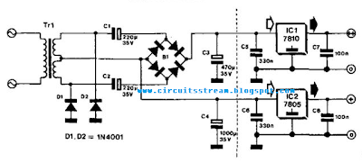
Simple Bridge Rectifier Circuit Diagram | Electronic Circuit Diagrams

Bridge Rectifier Circuit Diagram

half bridge rectifier - CircuitLab
Single Phase Rectification - Circuits Geek