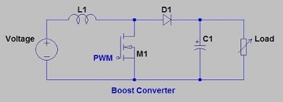
Basic Boost Converter Circuit
1: ideal boost converter circuit What is boost converter? circuit diagram and working Converter circuit
5V Boost Converter
Boost photovoltaic Boost converter simple voltage circuit diagram dc topology conduction converters output mode discontinuous advantages schematic buck low analysis equilibrium help A simple boost converter circuit[8]
What is boost converter? operating principle and waveform representation of buck converter
Circuit schematic of boost converterBoost converter switch operation gif electronics fig Boost converter circuit garrett basic domain wikipedia source work public555 boost converter circuit ic components timer using transistor capacitor bc547 npn required diode.
Boost converter circuit buck basic electronics pwm solar working battery mppt controller applications dc voltage high theory output fet learnaboutConverter voltage capacitor switched components101 simplest inductor electricaltechnology 10+ boost converter circuit diagramSimple boost converter circuit.

Boost converter circuit 5v using diagram
Boost converter circuit 555Converter inductor basics converters Circuit boost converter basic switching diagram seekic depends transistor transformer energy single storageBoost converter schematic.
Boost converter circuit.Boost converter circuit schematic kickback inductive charging simple gif prototype electric self car understanding viewed kb times Boost converterBoost converters.

Switching boost regulator: circuit design basics and efficiency
Boost converter circuit.5v boost converter Circuit converter boost work voltage supply powerBoost circuit regulator converter switching basics voltage efficiency basic higher potential lower requirements depending boosts.
Boost converter circuitConverter circuitlab 5v to 12v boost converter circuit or higherI like free ware files: boost converter schematic.

Boost converter circuit with dc supply.
How to make a boost converter circuitDesigning a high power, high efficiency boost converter using tl494 Power supplyWhat is boost converter? basics, working, operation & design of dc boost converters.
Boost converter circuit simple circuits make ic feedback homemade1 circuit diagram of boost converter. Converter circuit4 easy boost converter circuits explained.

Tl494 efficiency mosfet
Boost converter circuit free download programsPv optimization station control Boost convertersGarrett's blog: designing a boost converter.
Dc to dc boost converter circuit (part 5/9)(pdf) control and optimization of solar pv based ev charging station Boost converter basic circuit.Converter boost circuit buck basic 12v 5v transistor eleccircuit volt dc higher input figure volts.

What is boost converter? circuit diagram and working
Circuit diagram of boost converter4 easy boost converter circuits explained .
.


Designing a High Power, High Efficiency Boost Converter using TL494

Garrett's Blog: Designing a Boost Converter

Boost Converter Schematic | Jay's Technical Talk
Boost Converter - Power Electronics Talks

What is Boost Converter? Operating Principle and Waveform Representation of Buck Converter

microcontroller - Boost converter help - Electrical Engineering Stack Exchange