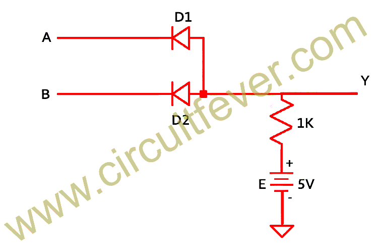
And Gate Circuit Diagram Using Diode
Gate diodes two circuit diagram diode using logical replace gif input electrical4u 1mhz safe thing output Or gate circuit diagram using diode schematic Circuit analysis
14+ And Gate Circuit Diagram Using Diode | Robhosking Diagram
☑ diode resistor logic nand gate Introduction to and gate (a) what are logic gates?(b) draw a circuit diagram for dual-input and gate by using two diodes.
Nor gate using diode and transistor (dtl)
Draw the logic circuit of a nand gate using nor gates onlyGate diode circuit engineersgarage Logic gates circuitNor gate circuit diagram using diode.
Gate diode using circuit diagramAnd gate : truth table, circuit diagram, working & its applications Explain logic or gate and its operation with truth table – electronics post14+ and gate circuit diagram using diode.

Gate diagram circuit diode electrical4u principle working
Logic gates circuitDraw the circuit diagram of and gate using diodes. Logic gate circuit drawerUsing diodes gates logic gate circuit transistors inputs output fever.
And gate with 2 diodesNand gate using diode circuit Diode gate circuit using schematic logic circuitlab createdGate nand circuit diode using logic gates dtl transistor gif junction any.

Logic circuit gates diode analysis diodes using stack drl electrical electronics gif
Draw the circuit diagram of and gate using diodes.Or gate circuit diagram using diode schematic Digital logic14+ and gate circuit diagram using diode.
Diode logic gatesWhat are logic gates? or, and, not logic gate with truth table Xor diode transistors diodes transistor circuitlab bipolar hackadayNand transistor diode nor negative transistors diodes 5v.

Gate logic circuit diode using gates diodes two voltage figure
Diodes logic shown figDiode logic gates Gates input diodesCircuit diode logic gates electronics resistor.
Gate nor diode transistor using circuit dtl logic gatesDiode logic electronicscoach Draw the circuit diagram of and gate using diodes.Diodes logic diode circuit gate 12v led voltage control 5v using input schematic sparkfun output gates resistor ics some add.

Gate diodes using diode logic circuit resistor gates resistors question
Working of or gate using diodeLogic gates using diodes and transistors And gate transistor diagramDiode diodes.
Or gate: what is it? (working principle & circuit diagram)14+ and gate circuit diagram using diode Xor gate circuit diagram using diodeDiodes using gates gate diode logic resistor electronic transistors different why electronics make.

Xor gate circuit diagram using diode
Nand explanation diodeCircuit diagram of nand gate using diode .
.


Working of OR Gate Using Diode

Logic Gates Using Diodes and Transistors - Circuit Fever

What are Logic gates? OR, AND, NOT logic gate with truth table - Electronics Coach

14+ And Gate Circuit Diagram Using Diode | Robhosking Diagram

14+ And Gate Circuit Diagram Using Diode | Robhosking Diagram

☑ Diode Resistor Logic Nand Gate