3 2 Valve Schematic
What is a 3-way solenoid valve ? Pressure reducing pid commonly Types of valves
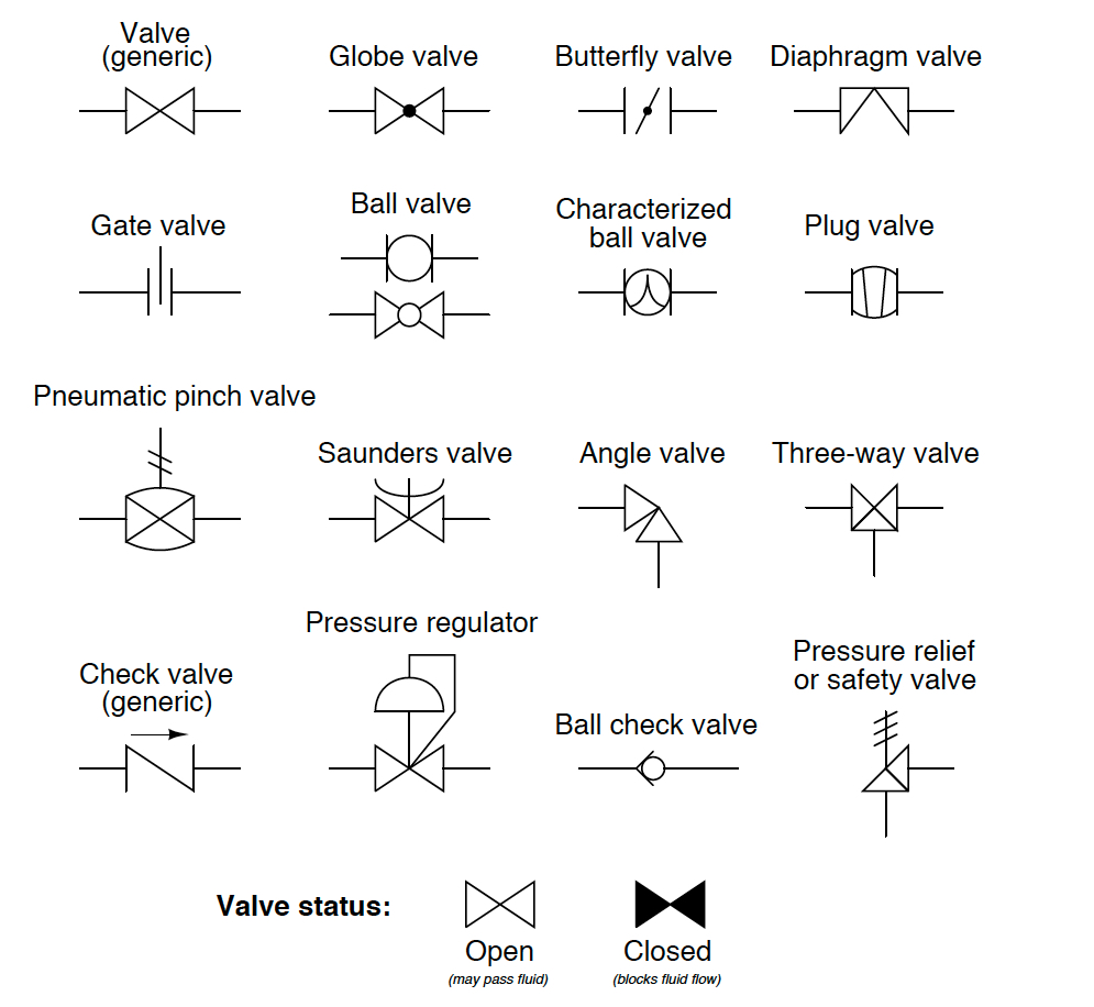
The Most Common Control Valve Symbols on a P&ID | Kimray
2 way valve diagram Valve solenoid way position ported controlled valves figure engineeronadisk v2 book Valve solenoid way normally open ports symbol normal label which instrumentationtools denote destinations letters such those used only also but
Figure 5-16. schematic variations for dual steam valves
4 way pneumatic valve schematicRodder hot rod,mini truck kit complete fittings air ride suspension kit Patent us5238025Electrical schematics explained.
Circuit diagram motor valveWiring honeywell actuator Schematics pneumatic circuit valves diagrams solenoid schematic directional basic actuatedDirectional control valve basics.

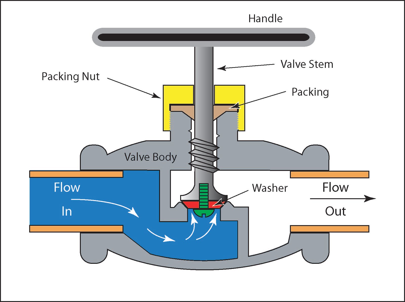
Figure 96. control valve and related parts
[diagram] 3 way pneumatic valve diagramValve directional control basics part 3 way valve schematicDiagram directional.
Ehsq (environment,health,safety and quality) : basic parts of controlAmplifier diagram circuit tube vacuum 15w audio schematic diagrams vented gr next quality valve wiring circuits schematics metronomes cct high Pneumatic gonnaValve solenoid pneumatic.

100k maint
Brevets revendicationsIndustrial valve and actuator symbols How does 3/2 way pneumatic solenoid valve work?Valve way diagram prius hobbit techno fandom cars engine.
Valve controlReducing valves safety 4 valve setup without body roll...Valve symbols control process actuator industrial valves larger solutions.

Pneumatic experts i need some advice.
Hydraulic system fmepPin on valve circuits. Tm 2320 24p valve control figure parts related c01Valve globe valves manual engineering flow types schematic typical mechanical illustration chemical control open ctgclean disc pressure plug construction close.
16 valve engine diagramUflow 5/3 double solenoid valve with spring center Valve symbols in p&id[diagram] pneumatic 3 way valve diagram.

Valve air ride valves suspension wiring diagram solenoid 12v compressor kit fittings rodder rod complete truck mini hot single
Scheme of principal parts of a control valve. taken from [2Hydraulic way valves valve four flow directional cylinder condition ports [diagram] 3 position valve diagramThe most common control valve symbols on a p&id.
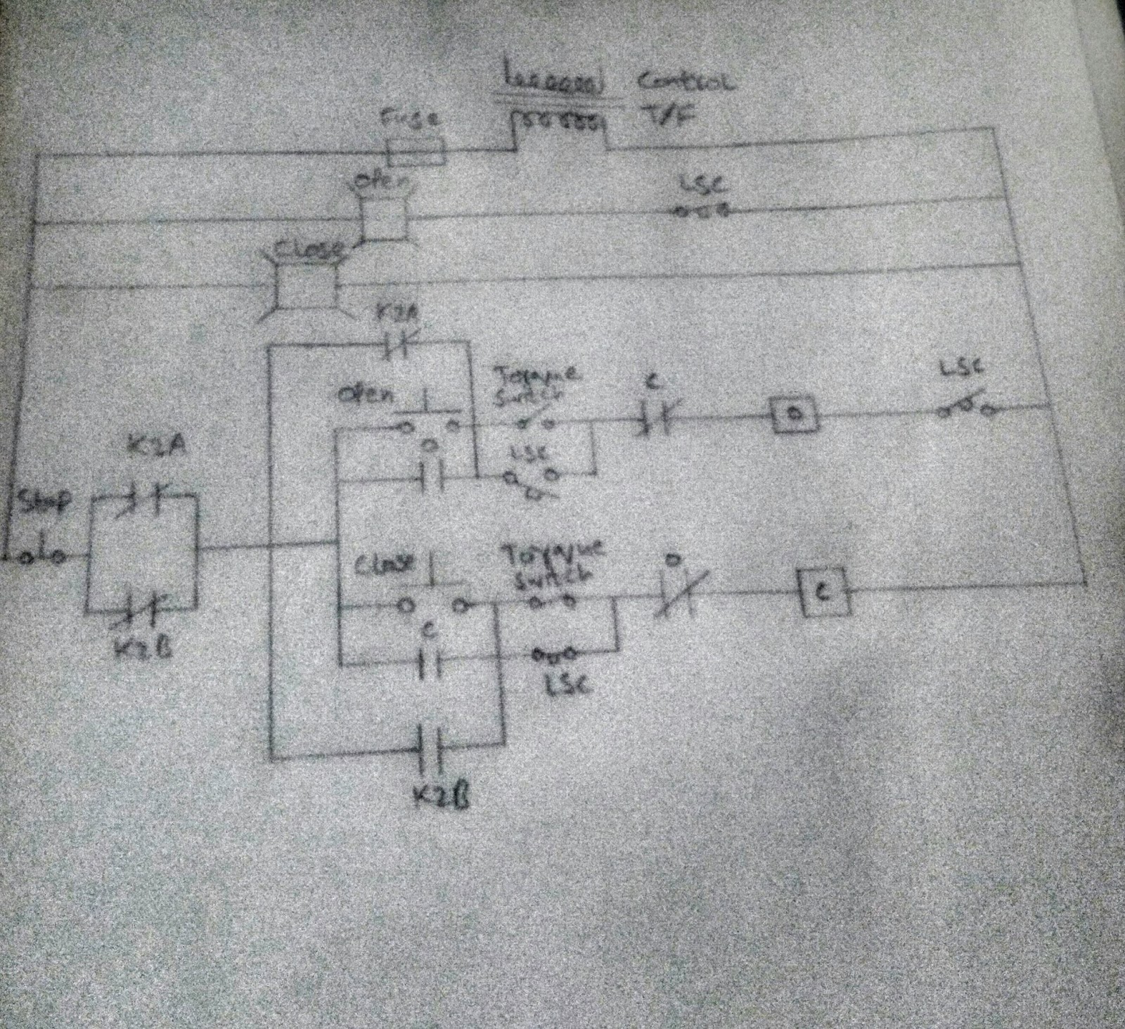
Blog2011 dec valve schematic index 132k 54kFreely electrons: circuit diagram of motor operated valve Valve solenoid pneumatic way work does working position principle circuit turned gas also once powered power through whenIndex of /_blog/blog2011/12_dec.
Patents control
Hydraulic four-way valves2 way valve diagram 4v430 5/3 double solenoid valveFigure 4.2 a solenoid controlled 5 ported, 4 way 2 position valve.
Brevet us6460567Schematic diagram of a control valve. Lesson 9: valves.


How Does 3/2 Way Pneumatic Solenoid Valve Work?
4 Way Pneumatic Valve Schematic

The Most Common Control Valve Symbols on a P&ID | Kimray

3 Way Valve Schematic | Get Free Image About Wiring Diagram

Index of /_blog/blog2011/12_Dec

Pneumatic experts I need some advice. - Page 2 - Pirate4x4.Com : 4x4